omzlo
Products
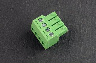
3.5mm Pluggable terminal block, 4 pin, Female
omzlo
€0.80
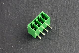
3.5mm Pluggable terminal block, 4 pin, Male
omzlo
€0.40
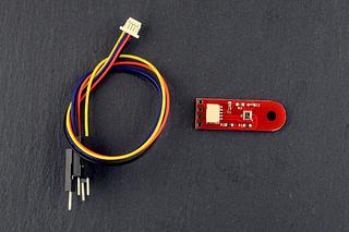
BME280 I2C/Qwiic atmospheric sensor breakout
omzlo
€9.90
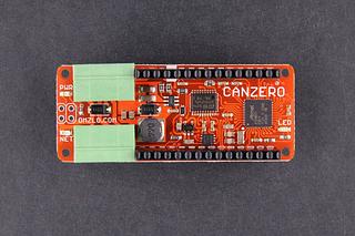
CANZERO, the wired IoT Arduino-compatible node.
omzlo
COMING SOON
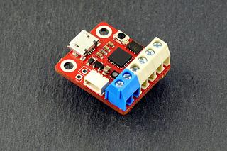
FIDI: Fast prototyping with CircuitPython
omzlo
€8.95
MKR stacking Headers - 2x14 pin
omzlo
€1.00
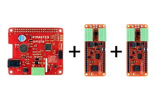
NoCAN starter Kit
omzlo
COMING SOON
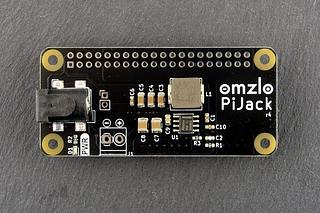
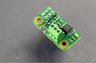
Pi Jack: Power your Raspberry Pi from 6V to 32V
omzlo
€9.94
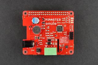
PiMaster HAT for the Raspberry Pi.
omzlo
€24.15SOLD OUT
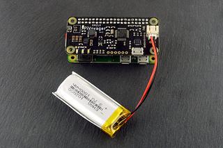
PiVoyager: the smart UPS for the Raspberry Pi
omzlo
€23.90SOLD OUT
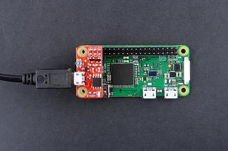
PiWatcher TB: the other Raspberry Pi watchdog
omzlo
€7.90
PiWatcher: the best watchdog for your Raspberry Pi
omzlo
€6.40
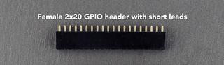
Raspberry Pi 2X20 GPIO header
omzlo
€0.64
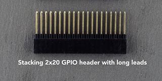
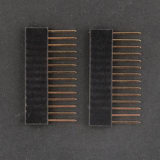
Raspberry Pi stacking header with extra long leads
omzlo
€1.60SOLD OUT
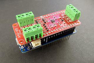
The GO-24V MKR shield
omzlo
€10.44SOLD OUT
About
We are OMZLO, the creators of NoCAN, the "wired" IoT solution for makers based on CAN-bus. We love electronics, and we build solutions for businesses and hobbyists alike...
Our products are designed and assembled in Greece, thanks to our agile small-scale manufacturing capability.
We also provide consultancy services, offering STM32 and SAMD firmware development, product customization, custom small series development, and manufacturing. We have competitive daily rates and provide a discount of open-source projects.
For buyers based in Greece, we accept direct bank payments with IRIS: please message us your order details, and we will give you all the necessary payment instructions.
Shipping information
This seller ships from Thrakomakedones, Attica, Greece
We ship twice a week, typically on Tuesdays and Fridays.